Please select a category below to find frequently asked questions about all things Scanivalve. Not finding the answers that you are looking for? Feel free to contact us!
What is the difference between an intelligent module and an analog module?
Scanivalve’ s “intelligent” measurement devices (DSA5000 and MPS4200 for gas, DSA3207/3307 for liquid, DTS4050 for temperature) are all-in-one data acquisition modules that perform all conversions from pressure, to voltage, to analog-to-digital converter counts, to an Engineering Unit. These modules have a built in processor that allows for an Ethernet connection, and memory for storing settings and coefficient conversion tables. All that is required is a power and Ethernet connection and data can be output to you in an ready-to-use Engineering Unit. These devices use an IP Address for TCP/IP Telnet communications and all controls are managed through this communication stream.
Analog measurement devices (ZOC modules, MPS4100, EIM, DSA3016) require an external data acquisition module for communications and conversions. These modules typically require two power sources (15 and 5Vdc), 4- to 6-bit CMOS addressing, and must read a voltage and RTD of the device. The data acquisition system is then responsible for the conversion of the voltage readings to a value that can be used by the end-user. Scanivalve does manufacture data acquisition systems, such as the DSM4000 and ERAD4000, that can communicate with an analog device and perform the conversion, however third-party systems can also be used. Analog devices are not equipped with processors or memory, and cannot be communicated with via Ethernet or serial connection.
What is the difference between Scanivalve “pressure types,” such as Differential, Gauge, or Absolute?
Scanivalve’s pressure scanners can come in a variety of pressure types that are meant for different types of pressure measurement applications. These different types may use different style sensors or valves for unique configurations.
Differential
Differential is the most common type of pressure measurement module that Scanivalve offers. Differential modules provide an input for each side of the pressure transducers (positive “+”, and negative ‘-“). The output from the sensor will be the differential pressure between the positive and negative inputs. Scanivalve does, however, have different variations of differential modules.
Common Differential (also known as Differential or Standard Differential)
This is the standard pressure type for most pressure modules. These modules provide a discrete input for the positive side of each sensor installed, and common “reference” input (single input for single range units, two inputs for dual range units) that is manifolded to the negative side of all sensors installed. These modules are best for applications where a differential pressure measurement is needed against a common reference pressure for all channels e.g., all channel plumbed to a test article and the common reference plumbed to the atmosphere or static port. When the reference port is left open to a static atmospheric pressure, these modules can be used in place of a “Gauge” pressure measurement application.
True Differential (also includes Individual Reference)
True differential (or Individual Reference) modules use the same sensors as the common differential modules. However, instead of a common reference port that is manifolded to the negative side of all sensors, a discrete port is provided for the negative side of each sensor. No common reference port is available, and each port will have a positive and negative port for each sensor. Each sensor will output a differential pressure between its discrete ports. These modules are best for applications where differential pressure measurements are needed, but each port is unique e.g., compressor stage testing where one channel is used to measure the different pressure between two stages (stage 1 and 2 for example use port 1+ and 1-). The next channel may be used to measure the differential pressure between stages 2 and 3 (uses ports 2+ and 2-).
Note: The major difference between True Differential and Individual Reference modules is the internal valving used in the module. When control pressure is applied to the internal calibration valve to switch the module into Calibrate mode (for calibrations or CALZs) , a true differential valve will short the negative ports to a single, common reference port. Individual Reference modules do not have valving to accomplish this.
Absolute
Absolute pressure scanners are offered in some Scanivalve pressure modules. Absolute pressure scanners have a discrete input for each sensor installed in the module. These sensors seal the negative side of the sensor in a vacuum to output an absolute pressure value. There is no reference port and pressure cannot be applied to the negative side of the sensor. All pressure output values are against vacuum pressure. An absolute module left open to atmosphere will read the atmospheric pressure in PSIA (such as 14.7PSIA). These modules are best used when an absolute pressure measurement is needed or when trying to measure pressure below atmospheric pressure e.g., Barometric, weather or meteorological studies.
Gauge
Scanivalve only offers Gauge type pressure scanners in the DSA3207 and DSA3207-PTP “all-media” pressure scanners. Gauge pressure sensors provide a discrete input for the positive side of each sensor installed. The negative side of the transducer is left open to the atmospheric pressure in the case of the pressure scanner module. The positive inputs are leak checked at tested, however the negative side is not as it is simply left open to measure the atmospheric pressure. It does not allow for pressure to be applied to the negative side of the sensor. These modules are not designed for use when measuring a “negative” gauge pressure (below atmospheric pressure), in which we would recommend a common differential module.
These modules are best used for applications where a gauge pressure measurement is needed e.g., measuring the gauge pressure of water in water pipes, measuring the pressure in tires, or chamber pressure.
What is “Px”? What is a Tubulation? What is “Tx”, “TCU”, “%FS”?
Scanivalve has many simplified terms or names for items specific to Scanivalve products. Here are the most common:
Px : Typically used to refer to a single pressure input or channel. You may see this in part numbers, like the MPS4264/64Px, which means the module has 64 Px, or channel, inputs. You may also see Px used on channels, such as Px 1 or Px 2, or used for positive and negaitve channel inputs i.e., Px +1 and Px -1 would be the positive and negative inputs for channel 1.
Tx : Typically used to refer to a single temperature input or channel. You may see this in part numbers, like the DTS4050/16Tx, which means the module has 16 Tx, or channel, inputs. You may also see Tx used on channels, such as Tx 1 or Tx 2.
Tubulation : A term used to describe a stainless steel or brass tube with a bulge, used primarily for pneumatic connections.
%FS : “Percent of Full-Scale.” This is the expression of accuracy based on the full scale, nominal pressure range of the module. It is used both to define a module’s accuracy limit and its actual accuracy. It is always calculated using the nominal pressure range of the module.
EU : “Engineering Units.” This is usually a variable in Scanivalve modules that determines whether the engineering unit conversion process will occur in the unit. If engineering units are not enabled, the device with output data in ADC (Analog-to-digital converter) counts. If engineering units are enabled, the module will take the ADC counts and convert them into the desired engineering units (PSI, kPa, Pa, BAR….) using the stored calibration coefficients.
TCU : “Thermal Control Unit.” An insulated enclosure used to maintain the temperature of an installed module to keep it within its operational temperature range. TCU’s can be equipped with heaters for operations of modules sub-zero temperatures, and sometimes with cooing kits for operation in hot environments.
For a full glossary of terms and words used by Scanivalve specific to Scanivalve products, please find a full, downloadable glossary here!
How often should I calibrate my pressure or temperature measurement device?
Measurement devices should be validated on a six month interval, and calibrated when needed for the best accuracy. Full Calibrations can be performed by Scanivalve in our factory. Field calibrations can be performed in the field using Scanvialve software, such as PressCal or TempCal. These programs are available to download from our website at no charge (requires accurate pressure standard or accurate voltage standard).
How do I upgrade the software or firmware of my intelligent module?
Software upgrades are available by speaking to the technical department at Scanivalve. If you are looking to update the firmware in your module, please reach out to us with your contact information and we can provide the necessary files.
To check the latest firmware version for your module, please refer to the module’s product webpage, and refer to the current user manual that can be reviewed. The first page will show the current firmware version. For procedures on updating the firmware of your module, please refer to the user manual for the Firmware Upload Procedure. Some modules will have different procedures, so please ensure that you have the correct user manual for your device.
I have lost my backup coefficients. What can I do?
Scanivalve maintains an extensive archive of coefficients and backup files for all modules that have been calibrated in our facility. Please contact us with the module number, configuration, and serial number, and we can provide any backup files available including coefficients, reports, or certifications.
How often should I perform a quick-zero calibration or “CALZ / CALB” on my pressure device?
Due to the nature of the piezoresistive sensors used in Scanivalve pressure measurement devices, it is recommended that a quick zero calibration (CALZ) be performed at least daily. Performing a quick zero more often will not cause any problems and is highly encouraged. There are no issues using the quick zero calibration in each instance before data is collected. Keep in mind, if the temperature of the module changes more than 5°C, a fresh quick zero should be performed. Zero offset corrections may become obsolete after several hours or after the module has changed temperatures.
Keep in mind that CALZs can be issued when using control pressures to place modules into CAL or Calibrate mode, or can be performed in a “Wind-Off” condition without control pressures. A “Wind-Off” condition is when all measurement inputs and/or reference inputs are open to the same static reference pressure and no air is being applied to the inputs, as it would be when a wind tunnel is not operating.
I can’t communicate with my module. What can I do?
There are many things that can be done if you cannot communicate with your intelligent device.
- Ensure that the device is powered on an the correct power is applied. See the module’s user manual for specifications on power requirements. Most modules have an LED indicator to signal that power is applied.
- Allow enough time for the module to properly and fully boot. While each module is different, it is best to wait for 1 – 2 minutes.
- Ensure all network connections are properly connected, whether this is from the Scanivalve device to a network switch, the network switch to the host computer, or the Scanivalve device to the host computer. This may require that the Ethernet cables and/or switch used are correctly tested for good communications.
- Ensure that the IP addresses used by the Scanivalve module and the host computer are compatible (see subsequent sections for details on finding or changing the IP address of your computer or device).
- Ensure that no two devices on the network are using the same IP address e.g., if the host computer and Scanivalve device have the same IP address (191.30.100.100), communications will not be possible.
- Ensure that any firewalls or anti-virus programs are not blocking unknown Telnet communications from unknown IP addresses (the primary means of communications from Scanivalve devices are established TCP/IP via Telnet port 23).
- Attempt to “ping” the device using Windows Command prompt to test the network connectivity.
- Use a different software program to establish an Ethernet connection, such as ScanTel, HyperTerminal, or PuTTY.
If these steps do not resolve the issue, the next step would be to establish a serial connection to confirm the IP address of the device, monitor the boot process for any errors or for boot completion, or to verify response from the device. Please review establishing a serial connection in the user manual of your module.
What is a compatible IP address?
The range of compatible IP addresses is defined by the subnet mask. The subnet mask digits of “255” define that the two IP addresses must have matching digits in those positions, and the subnet mask digit of “0” allows the two IP addresses to have unique values for those octets and still be compatible. The standard default subnet mask is 255.255.0.0. This default subnet mask requires that the IP address of the module and host computer must share the first two octets, or sets of numbers. The third and fourth octets of the IP address is variable with this subnet. No two devices on a single network can share the same IP address. Below are some examples of compatible and non-compatible IP addresses between devices:
Example of matching the first three octets: Subnet mask: 255.255.255.0 Host computer: 191.30.66.90 Scanivalve module: 191.30.66.100
Example of matching the first two octets: Subnet mask: 255.255.0.0 Host computer: 191.30.1.1 Scanivalve module: 191.30.66.125
Example of NON-COMPATIBLE IP addresses: Subnet mask: 255.255.255.0 Host computer: 191.30.1.1 Scanivalve module: 191.30.66.5
The subnet and IP addresses of two devices must follow these guidelines for proper communication.
What is the factory set IP address of my module?
Scanivalve will always pre-configure the IP address of every module. In the event that the IP address is not know, but the IP address has not changed since it was received from Scanivalve, you may be able to use the factory IP address to establish a connection.
Every intelligent Scanivalve device (unless otherwise specified) uses an IP address format of: 191.30.yyy.xxx
yyy is the product family code.
xxx is the last three digits of the serial number of the module.
To find the family code, please refer to the chart below.
| Module Name | Family Code (yyy) |
| DSA3017 | 5 |
| DSA3018 | 10 |
| DSAENCL3000 | 16 |
| DSA3019 | 19 |
| DSAENCL3100 | 21 |
| DSAENCL3002 | 26 |
| DSM3000/3200 | 30 |
| DSM3005/3205 | 35 |
| DSM3001 | 40 |
| RAD4000 | 40 |
| DSM4000 | 41 |
| SPC4000 | 44 |
| SPCENCL3000 | 45 |
| DSAENCL4000 | 46 |
| SPCENCL3002 | 50 |
| DTS3250/16Tx | 55 |
| DTS3250/32Tx | 60 |
| ENETCPM | 65 |
| ECM4000 | 66 |
| DSA3007 | 70 |
| DSA3207 | 75 |
| DSA3207-PTP | 77 |
| DSA3217 | 80 |
| DSA3217-PTP | 82 |
| DSA3218 | 85 |
| DSA3218-PTP | 87 |
| MPS4264 | 90 |
| MPS4232 | 95 |
| DTS4050/16Tx | 100 |
| DTS4050/32Tx | 105 |
| DTS4050/64Tx | 110 |
| DSA5000 | 130 |
| DTS3250/64Tx | 160 |
| DSM3400 | 190 |
| DSAENCL3200 | 216 |
How do I find the IP address of my module if it is not known?
Using a serial connection with an intelligent Scanivalve device is the best way to find the IP address of the module if it is lost or unknown. See the next FAQ bullet point for more information on making a serial connection.
If a serial connection is not possible, the only options are to test the last known IP address of the module, using the default, factory programmed IP address (previous FAQ bullet), or using the generic reset IP address value, which follows the factory set IP address, however the last octet of the IP address will be 100. If any of those do not work, then you must either make a serial connection, or send the module back to Scanivalve for evaluation.
How do I make a serial connection to my device to find the IP address?
Using a serial connection with an intelligent Scanivalve device is the best way to find the IP address of the module if it is lost or unknown. All Scanivalve intelligent modules provide a serial connector that will allow for RS232 serial communications. Using a terminal emulator of choice, such as HyperTerminal or PuTTY, the following settings can be used to communicate serially with most modules:
Bits per second (BAUD): 9600
Data bits: 8
Parity: none
Stop bits: 1
Flow control: none
Some modules may use a different BAUD rate. To find this, please refer to the user manual of this device.
Power cycling the module when a serial connection is active will usually show a boot process. At the end of a boot process in modules that use the VxWorks bootloader, the IP address of the module is shown.
For more modern modules, like the MPS series, DSA-PTP series, DSA/ENCL/ERAD4000 series, and DTS4050 series (and more), the command LIST IP can be used to find the bootloader properties of the module. If the serial connection is not working properly, please ensure the serial connection settings are correct, the cable and wiring is correct, and the COM port selected on the computer is correct. If possible, test another working module to see if the problem is with the module or with the connection.
If you are uncertain about making a serial connection, we do have a guide that can help setup a serial connection using puTTY; Click here.
How do I change the IP Address of my intelligent module?
All intelligent modules use a “static” IP address that can be set by the user. All modules have different procedures for this. Most Scanivalve modules have IP addresses located under the LIST IP group, which can be accessed via Ethernet or Serial connection (and changed as well). For older Scanivalve modules, the IP address can only be set using a serial connection.
Please refer to the user manual of your device to find the procedure on how to change the IP address.
Please note that although the following procedures can be used as general guidelines, it is strongly recommended that you consult your computer or operating system manufacturer directly for assistance on the proper procedure for configuring network settings.
How do I find the IP address of my computer?
Command Prompt Method
Windows 2000/XP/Vista/7/8.1/10
- On your keyboard, press Windows Logo+R keys simultaneously to bring up the Run dialog box.
- In the dialog box, type cmd to bring up the command prompt.
- In the command prompt, type:
Ipconfig<ENTER> to display your IP address settings.
MAC OS
- Navigate to your Applications folder and open Utilities.
- Double-click on Terminal to launch the command prompt.
- In the command prompt, type:
ipconfig getifaddr <en0 or en1><ENTER> to display the wired or wireless IP address settings.
Note: en0 is typically the wired Ethernet and en1 is typically the wireless Airport interface.
Graphical Method (MAC)
MAC OS 10.6/10.5
- From the Apple menu, select System Preferences.
- In System Preferences, from the View menu, select Network.
- In the Network preference window, click a network port (e.g., Ethernet, AirPort, etc). If you are connected, you’ll see your IP address settings under “Status:”
MAC OS 10.4
- From the Apple menu, select Location, and then Network Preferences.
- In the Network Preference window, next to “Show:”, select Network Status. You’ll see your network status and your IP address settings displayed.
Note: If you are experiencing difficulties, please contact your computer or operating system manufacturer for assistance.
How do I configure the network settings on my computer to use a static IP address?
Windows 7/8.1/10
- Navigate to the Control Panel and click Network and Sharing Center.
- Click Change Adapter Settings, right-click the Local Area Connection icon and select Properties.
Note: If you have more than one Local Area Connection icon, you may have more than one network card. It is also possible that you have an icon named Ethernet. Please ensure to select the correct Icon for the network card that is connected to the Scanivalve device or local network.
- Select Internet Protocol Version 4 (TCP/IPv4) and then click the Properties button.
- Then click the Use the following IP address radio button and assign your network adapter a static IP address and subnet mask (default gateway and DNS server not required).
- Click OK and then close all windows.
Windows Vista
- Go into the Control Panel, click Network and Internet.
- Click Manage Network Connections, right-click the Local Area Connection icon and click Properties.
- Click Internet Protocol Version (TCP/IPv4) and then click Properties.
- Then click the Use the following IP address radio button and assign your network adapter a static IP address.
- Click OK and then close all windows.
Windows XP/2000
- Go into the Control Panel, double-click the Network Connections icon
- Right-click the Local Area Connection icon and the click Properties.
- Click Internet Protocol (TCP/IP) and click Properties.
- Then click the Use the following IP address radio button and assign your network adapter a static IP address.
- Click OK and then close all windows.
MAC OS 10.4/10.5/10.6
- From the Apple, drop-down list, select System Preferences.
- Click the Network icon.
- From the Location drop-down list, select Automatic.
- Select and view your Ethernet connection.
- In:
- MAC OS 10.4; from the Show drop-down list, select Built-in Ethernet and select the TCP/IP tab.
- In MAC OS 10.5/10.6; in the left column, select Ethernet.
- Configure TCP/IP to use a static IP in:
- MAC 10.4; from the Configure IPv4, drop-down list, select Manually and assign your network adapter a static IP address. Then click the “Apply Now” button.
- MAC 10.5/10.6; from the Configure drop-down list, select Manually and assign your network adapter a static IP address. Then click the “Apply” button.
- Restart your computer.
Note: If you are experiencing difficulties, please contact your computer or operating system manufacturer for assistance.
How do I find the MAC address of my computer?
Windows 2000/XP/Vista/7/8.1/10
- On your keyboard, press Windows Logo+R keys simultaneously to bring up the Run dialog box.
- In the dialog box, type cmd to bring up the command prompt.
- In the command prompt, type:
Ipconfig<ENTER> to display your IP address and MAC settings.
Alternatively, you can type getmac –v to display the MAC addresses only. In MAC OS 10.4,
- Apple Menu > System Preferences > Network
- From the Show menu, select Built-in Ethernet.
- On the Ethernet tab, the Ethernet ID is your MAC Address.
In MAC OS 10.5/10.6,
- Apple Menu > System Preferences > Network
- Select Ethernet from the list on the left.
- Click the Advanced button.
- On the Ethernet tab, the Ethernet ID is your MAC Address.
How do I use the ‘PING’ command in Command Prompt to check for network device connectivity?
Windows 2000/XP/Vista/7/8.1/10
- On your keyboard, press Windows Logo+R keys simultaneously to bring up the Run dialog box.
- In the dialog box, type cmd to bring up the command prompt.
- In the command prompt, type:
ping <ipaddress><ENTER> with the <ipaddress> being the IP address you want ping and check for connectivity (e.g., the Scanivalve module’s IP address)
Example: Usage of ping command and successful replies from device.
C:\Users> ping 191.30.90.100 Pinging 191.30.90.100 with 32 bytes of data:
Reply from 191.30.90.100: bytes=32 time<1ms TTL=64
Reply from 191.30.90.100: bytes=32 time<1ms TTL=64
Reply from 191.30.90.100: bytes=32 time<1ms TTL=64
Reply from 191.30.90.100: bytes=32 time<1ms TTL=64
Ping statistics for 191.30.90.100: Packets: Sent = 4, Received = 4, Lost = 0 (0% loss),
Approximate round trip times in milli-seconds: Minimum = 0ms, Maximum = 0ms, Average = 0ms
MAC OS X
- Navigate to your Applications folder and open Utilities.
- Double-click on Terminal to launch the command prompt.
- In the command prompt, type ping –c <#> <ip_address> with the <#> ping being the number of times you want to ping and the <ip_address> being the IP address you want ping and check for connectivity.
Example: ping –c 4 191.30.90.100
Note: If you are experiencing difficulties, please contact your computer or operating system manufacturer for assistance.
How do the valves in Scanivalve Modules operate?
All ZOC16, ZOC17, and DSA gas pressure modules have four way valves for each sensor. Application of a control pressure causes a piston in each valve to compress an o-ring, forming an air tight seal. All of these valves are capable of, and have been tested to, a minimum of one million operations.
All ZOC 22, 23 and 33 modules also have four way valves for each sensor. These valves use inflatable bladders instead of pistons that “pinch” internal tubing. Although the method is somewhat different, the bladders are able to form air tight seals and require a lower control pressure that the DSA modules to operate.
The MPS series has a new internal “shuttle” valve that offers two positions to cover all pneumatic states. The valve can be configured to require one pneumatic control pressure to shift the valve (similar to the DSA series), or a bi-directional valve that requires two pneumatic control pressures (similar to the ZOC series).
What are control pressures?
Control pressures are simply a pneumatic ‘muscle’ pressure used to switch the internal valves in a module from one pneumatic state to another. The typical pneumatic states include:
- Isolate mode
Isolate is used to close off the Px inputs (each discrete pneumatic channel inputs) and isolate the sensors from any input pressure. This can be used to protect the sensors from excess pressure or contaminants. - Calibrate (also known as CAL) mode
This mode will internally manifold the positive side of each sensor in the module to a single CAL (calibration) port. This allows a single pressure to be applied to all sensors in the module evenly.
In most cases, the Reference port of the module is unaffected by the Calibration valve. This is not true with True Differential (DPx) modules (DSA and ZOC17 only). - Measurement (also known as Operate or Px) mode
This is the standard mode for operation, measurement, or collecting data. Each Px Input (discrete pneumatic channel input) is connected to it’s own sensor. - Purge mode
This mode allows for the input’s to be purged of any contaminants, moisture, and more. When in this mode, a pressure can be supplied to a single port than will exit out each of the Px Inputs. This can be used to clear the input lines of contaminants, moisture, dust and debris to help protect the sensitive components when operating in an environment that may cause damage to the sensitive electronic components (such as steam turbine, in-flight aero tests, or PIV testing).
Electronic signals are not required to switch these valves (with the exception of the MPS/EPx and DSA5000). Control pressures should be clean, dry instrument grade air.
What are control pressure requirements for my module?
Different modules require different control pressures to operate the internal valving.
The ZOC16, ZOC17, and DSA gas pressure modules require 90-120psi control pressure (the allowed range varies based on the pressure range of the module i.e., a low pressure module may only need 90psi, where a high pressure module requires 120psi).
The ZOC22, 23, and 33 modules require 55-65psi control pressure.
The MPS4000 series can be configured to accept 65psi (CPx configuration like the ZOC22, 23, and 33 modules), or 90-120psi (NPx configuration like the DSA series).
What quality air should be used for control pressures?
Typically for control pressure, Instrument Air Quality is key to longevity of the internal pneumatic valves. A standard factory, shop, airline is not recommended as these can contain particulate, oil, and water contaminates. Alternate sources of instrument grade air can also be found in Nitrogen or compressed air cylinders. If you are unable to get access to cylinder Nitrogen or Compressed air then your compressor should be filtered and dried by a suitable means. For more information on “instrument grade air”, please refer to ISA specification ISA-S7-3.
Note: There are many different levels to clean, dry air. Some systems for very clean, dry air can be very expensive to install. It is best to determine the air system that best suits your needs.
Do control pressures have to be applied at all times?
All DSA series, ZOC16, and ZOC17 modules use ”normally open” valves — that is, no control pressure is required for the module to be in ‘operate” or ‘measurement’ mode. Control pressures are only required to switch the valves to the other modes of operation (isolate, calibrate, or purge). The control pressure used for these modules must be 90 to 120psi depending on the pressure range of the module.
All ZOC22, ZOC23, and ZOC33 modules require a control pressure for each mode of operation. The control pressure for these modules must be 55 to 65 psi. If no control pressure is applied, the module is in ‘purge’ mode, where all inputs are open.
The MPS4000 NPx configuration require that 90-120psi is continuously applied to change the valve state to CAL/PRG/Isolate. It does not require control pressure for measurement mode. The MPS4000 CPx configuration is similar to the ZOC series, however, control pressure does not need to be continuously applied. Applying 65psi for a minimum of two seconds will shift the shuttle into the desired valve state. In high vibration environments, it may be required to leave control pressure on to ensure the valve stays in place.
How do the control pressures operate the valves?
Each module requires two or three control pressures to operate the valves, depending on the valve logic. All control pressure applied is non-flowing and only fills a volume.
ZOC16, ZOC17 and all DSA modules require three pressures. Two of the pressures control the normal valve modes (CTL1 and CTL2). The third pressure controls a separate purge valve (PRG CTL). The pressures applied will activate different internal pistons to change the pneumatic routing in the valve block and form leak tight seals against O-rings for the duration of the valve state change.
ZOC22, ZOC23, and ZOC33 modules also require two or three control pressures. The standard versions of these modules require two control pressures (PxCTL and CALCTL). The Duplex versions of these modules require a third control pressure to operate the Duplex valve (PxA, PxB, and CALCTL). The valves in these modules are “bladders” that inflate to pinch internal tubing to change the pneumatic state. When no control pressure is applied, the module is in ‘Purge’ mode, where all inputs are flowing.
The MPS4000 modules require one or two control pressures. The CPx configuration of the MPS4000 series is similar to the ZOC series and requires two control pressures (PxCTL and CALCTL). The NPx version only requires one control pressure (CALCTL) as the shuttle is held in Measurement mode using an internal spring. When control pressure is applied, it changes the valve state, depressing the spring. When control pressure is vented, the spring will move the shuttle back to measurement mode. This is similar to a DSA operation. The different modes of operation are obtained by applying the control pressures in a logical sequence.
Truth Tables may be found in the appropriate module hardware manual that show the logic required for proper operation.
Can my module be serviced, repaired, or calibrated?
Scanivalve has provided millions of channels of measurement instrumentation since 1955. We have many discontinued or obsolete products that may no longer be supported or serviced. All information on legacy products, including end-of-life, repairability, replacement modules, and more can be found on the Legacy Product Information page.
The following module series or devices are considered active and are fully serviceable:
DSA5000
DSA-PTP
DTS4050
ECM4000
MPS4000 & TCU
DSM4000
ENCL4000 / DSA3016
ERAD4000
SPC4050 / SPT4050 / SPCPLU
ZOC17 & TCU
ZOCEIM
PDM1500 / PDM5000 / MPSPDM4500
If your module was not listed, please check the Legacy Product information page for information on your module. We can still service and repair some modules beyond their end-of-life and discontinued date. If you cannot find your product, please contact us with your module, part number, and serial number.
Who do I contact for service, return, or repair information?
For product support, technical information, or extended troubleshooting, please contact Technical Support by:
- Filling out and submitting our Contact Us form
- Emailing techsupport@scanivalve.com
- Calling 1 (800) 935-5151 extension 253
For return authorization, status of a current return, or for service information please contact Repairs Department by:
- Filling out and submitting our Product Return form
- Emailing repairs@scanivalve.com
- Calling 1 (800) 935-5151 extension 255
For spare parts, shipping or pricing information, please contact Customer Service by:
- Filling out and submitting our Contact Us form
- Emailing orders@scanivalve.com
- Calling 1 (800) 935-5151 extension 248
If you are not sure who to contact:
- Fill out and submit our Contact Us form
- Email scanco@scanivalve.com
- Calling 1 (800) 935-5151 and dial the operator (0)
How long do repairs, service, and calibrations take?
The lead time on repairs and calibrations will vary based on the type of module, the number of modules returned, the needed repairs and part availability, and our current workload. It is recommended that you contact us prior to returning any equipment to avoid any unexpected delays. Please contact us via our Contact form, email, or by phone with your equipment, serial number(s), and reason for return so we can provide you with an estimated lead time.
Please note that any estimate provided is only an estimate. Due to the nature of measurement instrumentation, we cannot know the current condition of the device until it has been evaluated by our service department. Often times, we cannot accurately estimate the time frame for most repairs as we can only classify the repair as “Completed” once the module passes a calibration and all post-calibration tests. Even after initial repairs, modules can fail calibration due to other needed repairs that were not found prior to the calibration. We will, however, do our best to keep you informed on the status of your return and will return the equipment to you as soon as possible.
How do I return my module for repair or calibration?
Please fill out our Product Return Form on our website, in full. You can click on the previous link or find the link to the form in the bottom right hand corner of our website (“Product Return”). Please include as much information about the return as possible, including direct contact information in case we need to get a hold of you. Once the form is submitted, the form will generate an RMA or Product Return ID number that can be used to track your return. An atuo-generated email will then be sent to the email address entered in the form with additional return information. If you do not receive the email, please check your Junk or Spam mail folder.
Please print out the auto-generated email and include it with the module’s packaging. Please ship the module(s) and the printed email to:
Scanivalve Corporation
ATTN: Repairs Department
1722 North Madson Street
Liberty Lake, Washington, 99019
1 (800) 935-5151
If a product return form is not submitted, or the printed copy is not included with the package, this will delay the repair time.
How do you install plastic tubing to bulged or barbed tubulations?
See our tubing installation drawing for information on installing tubulations, plastic tubing, and using our tubing tools.
What are the power requirements?
DSA5000 modules with no heaters require 9 to 36Vdc at 12W.
DSA5000 modules with the optional installed heater require 18 to 36Vdc at 85W for full heater operation, however, the consumption will drop to 12W if the heater is off.
How do the valves in DSA modules work?
All DSA5000 pressure scanners have two “big block” valves installed in each module. Each “big block” valve services 8 channels, which include one four-way valve for each sensor. Application of different control pressures cause a piston in each valve to compress an o-ring, forming an airtight seal and changing the direction of flow. All of these valves are capable of, and have been tested to, a minimum of one million operations.
How do control pressures operate the valves?
Each module requires a 90-120psi control pressure source to operate the valves. This control pressure is then directed and applied with the use of internal solenoids to activate a particular valve to change the “mode’ of the module or change the flow paths. All solenoids are controlled via software commands. These three solenoids control:
CTL1 (Control 1) – Isolate valve – this valve closes the flow path from the pressure inputs to the transducer
CTL2 (Control 2) – Calibrate valve – this valve opens a path from the CAL port to each channel path
PRGCTL (Purge Control) – Purge valve – this valve opens a path from the PRG supply port the channel path
The path order of these vales goes: Channel Input (Px Input) –> PRGCTL –> CTL1 –> CTL2 –> Transducer.
These valves are used to configure the different modes of operation by applying the control pressures in a logical sequence. These modes are:
Measurement (PX) Mode = CTL1, CTL2, and PRGCTL OFF
Calibrate (CAL) Mode = CTL1 and CTL2 ON, PRGCTL OFF
Purge (PRG) Mode = CTL1, CTL2, and PRGCTL ON
Isolate (ISO) Mode = CTL1 ON, CTL2 and PRGCTL OFF
Valve logic drawings, truth tables, and port descriptions can be found in the DSA5000 manual.
Is it possible to minimize the number of control pressures needed?
In the design of the DSA5000, only one 90-120PSI regulated control source is needed for standard operations.
In the event that the module does not need to change modes – calibrations, purging or otherwise, a control source is not needed. The module, without control pressure, will always remain in measurement (Px) mode.
Do control pressures have to be applied at all times?
No – DSA5000 modules use ”normally open” valves — that is, no control pressure is required for the module to be in operate or measurement (Px) mode. Control pressures are only required to switch the valves to the other modes of operation (isolate, calibrate, or purge). The control pressure used must be 90 to 120psi depending on the pressure range of the module.
How often should I calibrate the module?
DSA modules should be validated on a six month interval, and calibrated when needed for the best accuracy. Scanivalve provides a utility program for customers who can perform their own validations and calibrations using a high-accuracy pressure standard, or a Scanivalve SPC calibrator. This allows customer to maintain their modules in the field. This program is called xxxxxx and may be downloaded from our website at no charge.
What are the power requirements?
DSA3200, 3300, and PTP series modules (with no heaters) require 28 ±8Vdc at 8W. DSA modules with an optional installed heater generally require 28 ±8Vdc at 40W for full heater operation, however will drop to 8W if the heater is off). DSA3016 modules are powered by a DSAENCL module and require ±15Vdc and +5Vdc from the ENCL.
How do the valves in DSA modules work?
All ZOC16, ZOC17, and DSA gas measurement modules have four way valves for each sensor. Application of a control pressure causes a piston in each valve to compress an o-ring, forming an air tight seal. All of these valves are capable of, and have been tested to, a minimum of one million operations.
Do DSA3207 and 3307 modules have the same valving as DSA gas modules?
No – the liquid variants of the DSA series scanners (3207 and 3307) do not have the same pneumatic valving that the gas pressure measurement devices have. Each DSA3207 and 3307 does, however, have a purge or bleed valve to allow for purging or bleeding of the input lines. For calibrations, all similar pressure range channels must be manifolded externally.
How do control pressures operate the valves?
Each module requires two or three 90-120psi control pressures to operate the valves, depending on the valve logic. ZOC16, ZOC17 and all DSA modules require three pressures. Two of the pressures control the normal valve modes. The third pressure controls a separate purge valve.
For most DSA products:
CTL1 (Control 1) – Isolate
CTL2 (Control 2) – Calibrate
PRGCTL (Purge Control) – Purge
The different modes of operation are obtained by applying the control pressures in a logical sequence. Truth Tables may be found in the appropriate module hardware manual that show the logic required for proper operation.
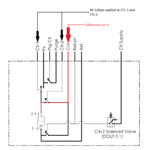
Measurement Mode
Calibrate Mode
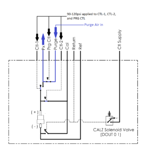
Purge Mode
Is it possible to minimize the number of control pressures needed?
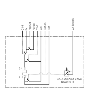
In some cases, yes! For DSA modules, a single control pressure may be used for “Zero Calibrations,” or CALZs. This requires a Quick-Zero jumper to manifold CTL1, CTL2, and RTN (return) together. A single control pressure is connected to the CTL SUPPLY port. When a CALZ is executed, an internal solenoid will flow this pressure to the RTN port, placing the module into “Calibrate’ mode until the CALZ is completed. Alternatively, CTL 1 and CTL 2 may be applied from the same source without using the quick-zero jumper to switch the module into the Calibration mode.
Do control pressures have to be applied at all times?
In most cases, no! All DSA series, ZOC16, and ZOC17 modules use ”normally open” valves — that is, no control pressure is required for the module to be in ‘operate” or ‘measurement’ mode. Control pressures are only required to switch the valves to the other modes of operation (isolate, calibrate, or purge). The control pressure used for these modules must be 90 to 120psi depending on the pressure range of the module.
How often should I calibrate the module?
DSA modules should be validated on a six month interval, and calibrated when needed for the best accuracy. Scanivalve provides a utility program for customers who can perform their own validations and calibrations using a high-accuracy pressure standard, or a Scanivalve SPC calibrator. This allows customer to maintain their modules in the field. This program is called PressCal and may be downloaded from our website at no charge.
How do I upload coefficients to my module?
Note: Firewall and anti-virus programs will sometimes block connections to Scanivalve devices. It may be necessary to disable these temporarily for these procedures.
For all non “PTP” modules:
Using ScanTel:
- Open ScanTel. To configure the connection, click on the “Configuration” button in the top menu bar. Enter the IP Address of the DSA module, set the “Upload Line Delay in MS” field to 30 milliseconds. Verify that the “Device Type” is set as a DSA. Click “OK”.
- In the top menu bar, click the Connect/Disconnect button. Verify that the connection status at the bottom of the window is “Connected.”
- Send the command “DELETE 0 72”. Wait approximately 5 seconds, then send the command “SAVE.”
- In the top menu bar of ScanTel, click File > Upload ASCII File… Browse to and select the coefficient file you wish to upload. The upload process will begin.
- Once the coefficients have been uploaded, you must create the calculated coefficients. Send the command “FILL” and wait. Use the STATUS command and wait for STATUS: READY (this process can be slow and take a few minutes).
- Send the command SAVE and wait.
- Verify the coefficients in the module are correct buy issuing the command “LIST M 0 72 1”. The DSA should return data in the following format. INSERT 0 1 -16.45000 -22000 M
Using HyperTerminal:
- Open HyperTerminal. When prompted, enter the name of the connection and click “OK.”
- When prompted, in the “connect to” drop-down menu, select “TCP/IP (Winsock). Enter the IP address of the DSA module in the “Host Address” field and 23 in the “Port” field. Click “OK.”
- In the upper left corner, click File > Properties. In the window that opens, click on the “Settings” tab, then click the “ASCII Setup” button.
- Check both the “Send line ends with line feeds” and the “Echo typed characters locally” boxes. In the “Line Delay” field, enter 30 milliseconds. Click “OK” on the ASCII Setup window and the Properties window.
- Send the command “DELETE 0 72”. Wait approximately 5 seconds, then send the command “SAVE.”
- In the top menu bar, click Transfer > Send Text File… Browse to and select the coefficient file you wish to upload. Note: you may have to change the “File Type” to “All Files (*.*)’ in order to select to coefficient file. The upload process will begin.
- Once the coefficients have been uploaded, you must create the calculated coefficients. Send the command “FILL” and wait. Use the STATUS command and wait for STATUS: READY (this process can be slow and take a few minutes).
- Send the command SAVE and wait.
- Verify the coefficients in the module are correct buy issuing the command “LIST M 0 72 1”. The DSA should return data in the following format. INSERT 0 1 -16.45000 -22000 M
For all “PTP” modules:
- Open ScanTel or HyperTerminal and establish a Ethernet connection (see steps in either of the procedures above).
- Send the command “DELETE 0 72”. Wait approximately 5 seconds, then send the command “SAVE.” Use the STATUS command to wait for STATUS; READY.
- Power off and back on thee DSA-PTP.
- Once the module has booted, open Windows File Explorer. In the address bar, type: FTP://<ipaddress> and hit enter.
- Open another instance of Windows File Explorer and navigate to the coefficient file (Cal.cfg). Copy and paste this file into the FTP connection to the DSA-PTP. Wait for the upload to complete.
- Power off and back on the DSA-PTP.
- Once the module has booted, establish an Ethernet connection to the DSA-PTP using ScanTel or Hyperterminal.
- Issue the command “SAVE.”
These procedures are also listed in the DSA and DSA-PTP manuals. Please refer to the user manual for any additional steps or information.
What are the power requirements?
The DTS4050/16Tx module requires 28Vdc at .58A. If an optional heater is installed, the power consumption may be as high as 1.6A @ 28Vdc while the heater is operating. The DTS4050/32Tx module requires 28Vdc at .83A. If an optional heater is installed, ,the power consumption may be as high as 4.8A @ 28Vdc while the heater is operating. The DTS4050/64Tx module requires 28Vdc at 1.45A. The heater option is not available for this model.
How often should I calibrate the module?
DTS modules should be validated on a six month interval, and calibrated when needed for the best accuracy. Calibrations can be performed by Scanivalve at the factory or by a user in the field. Each DTS is calibrated after manufacture before it is shipped. Scanivalve provides a utility program for customers who can perform their own validations and calibrations using a high-accuracy voltage standard. This program is called TempCal and may be downloaded from our website at no charge.
The TempCal software calibrates the voltage A/Ds in the DTS module. It can be operated in either automatic or manual mode depending on the voltage standard being used. In order to calibrate a DTS using TempCal, a calibration harness is required. The calibration harness can be ordered from Scanivalve using the following part numbers: 21079-1 (for 16 channel DTS modules) 21079-2 (for 32 channel DTS modules) 21079-3 (for 64 channel DTS modules)
In addition to the calibration harness, a host computer running Windows 7/8/10 and a DC voltage standard with a range of -10mV to +131mV and an accuracy of ±1.5μV or better is required. The procedure for performing a voltage calibration on a DTS using TempCal can be found in the TempCal software manual.
TempCal does not perform a recalibration of the physical RTDs. Calibration of the RTDs can be completed on a five year interval, however is usually not required.
What are the power requirements?
MPS4264 modules with a pneumatic configuration require +9 to 36Vdc at 3.5W. MPS4264 modules with the electric valve configuration require +18 to 36Vdc at 5.5W.
MPS4232 modules (valveless) require +5 to 36Vdc at 3.5W.
MPSTCUs with heaters require 20-30Vdc at 45W.
MPS4100 modules are analog modules that require ±15Vdc, +5Vdc, CMOS addressing and the ability to read and covert voltages (see General Module Information > What is the difference between intelligent and analog modules for more information).
How do the valves in MPS modules work?
All MPS 64-channel modules have an integral valve that uses a “shuttle” to change the pneumatic logic of the MPS module. This shuttle will actuate to switch the module between measurement mode, and Calbrate/Isolate/Purge (all the same mode).
In all CPx configurations, the shuttle is bi-directional, require a control pressure to move the shuttle from one side to the other. This method is similar to the operation of a ZOC module.
In all NPx configurations, the shuttle is normally in measurement mode, similar to a DSA. When control pressure is applied, the shuttle will actuate placing the module in a different state as long as the control pressure is applied. When control pressure is removed, the valve is actuated back to measurement mode by an internal spring.
In EPx configuration (MPS4264 only), and internal motor and gear actuate the internal shuttle, which is controlled via software commands. No control pressure or pneumatic source is required for this module.
The MPS4232 is valveless and does not require any control pressure. There is only one state in this module, which is measurement mode.
What are the power requirements?
DSAECNL4000’s have a built in AC/DC power module and accept a 110-230VAC input, 50-60hz, 100VA.
It is recommended that surge protection be used on the AC power connection to the DSAENCL. It is recommended to use a device that conforms to the UL 1449, 3rd edition standard for surge protection devices. The device must have a clamping voltage of 330V and an energy absorption rating of 600 joules or higher. Please see the DSAENCL4000 Manual for more details.
The ENCL has stopped responding, but appears to be operating. What can I do?
It is likely that the Ethernet link has been compromised. Attempt to open a new Telnet connection to the DSAECNL. The DSAENCL will accept a second Telnet connection and close the first, broken connection.
If this does not work, the DSAENCL should be power cycled.
Can I remove or swap a DSA3016 module when the DSAENCL is on?
Yes – as long as the DSA3016 in the ENCL has a operating power switch.
If a module is to be swapped or removed; vent any control pressures that may be applied to the DSAECNL or DSA3016s. If using the ENCL for Control pressure, simply issue the commands: DOUT 6 0, DOUT 7 0, and DOUT 8 0. Power off the DSA3016 (green power button on the front of the DSA), remove the screws that fasten the DSA to the ENCL, and remove the DSA. After a module has been removed or changed, connect to the DSAENCL and issue the command: LIST SYS U to update the ENCL.
Warning: Do not remove a DSA3016 without powering down the module or powering down the DSAENCL. This could damage the ENCL or DSA3016.
Does my ENCL support the PTP update?
The DSAENCL4000 firmware version 5.25 was the first release with PTP enabled. For PTP to operate, the DSAENCL must have hardware that will work, which may not be true in older modules.
You can still upgrade the firmware to the latest version in your ENCL as the version is backward compatible. After the firmware update, issue the command; GETTIME and asses the response from the ENCL.
If the date/time listed is a believable date near 1970/1/1 or 2015/1/1, then your ENCL is hardware compatible.
If the date/time is a very random date and time, and subsequent GETTIME commands do not show the time updating, then the ENCL is nor hardware compatible.
If you find your ENCL to be non-compatible with PTP, please contact Scanivalve as we can perform a hardware change on your ENCL to allow the use of PTP.
What are the power requirements?
DSM modules requires 9-36VDC. The power draw depends on the amount of modules connected to the DSM, however this should not exceed 44 watts.
Can I remove or swap a ZOC or MPS analog module when the DSM is on?
No – the DSM should be powered off whenever a connection is changed between the DSM and the analog modules. This includes swapping modules, cables, or positions.
Warning: Do not remove a ZOC or MPS modules without powering down the DSM. This could damage the DSM or the analog module.
Does my DSM support the PTP update?
The DSM4000 firmware version 2.16 was the first release with PTP enabled. For PTP to operate, the DSM must have hardware that will work, which may not be true in older modules.
You can still upgrade the firmware to the latest version in your DSM as the version is backward compatible. After the firmware update, issue the command; GETTIME and asses the response from the DSM.
If the date/time listed is a believable date near 1970/1/1 or 2015/1/1, then your DSM is hardware compatible.
If the date/time is a very random date and time, and subsequent GETTIME commands do not show the time updating, then the DSM is nor hardware compatible.
If you find your DSM to be non-compatible with PTP, please contact Scanivalve as we can perform a hardware change on your DSM to allow the use of PTP.
Please note that the ZOC22, 23, and 33 are discontinued.
What are the power requirements?
All ZOC modules require + 15Vdc and -15 Vdc for operation. This voltage does not need to be instrument grade. Sensor excitation voltage is developed on board the module.
How do I address the modules?
Addressing is a 4 to 6 bit address line depending on the number of sensors in the module (4-bit for 16, 5-bit for 32, 6-bit for 64). All address line inputs are pulled up to the +15 Vdc input.
How do I calibrate the modules?
The modules may be calibrated by applying the correct control pressure to switch the module to the Calibrate mode. Calibration pressures may be applied to all sensors from the CAL input. It is recommended that a second order polynomial be used to characterize each sensor for the best accuracy.
How often should I calibrate the modules?
ZOC pressure modules will show a considerable amount of drift unless the module is installed in a Thermal Control Unit. For best accuracy, a ZOC module should be re-zeroed before each data point. Calibration should be checked prior to taking data. Scanivalve Corp provides a utility program for customers who can perform their own calibrations. This program is called PressCal and may be downloaded from this website at no charge.
What is the difference between Muxed, Muxless, and APC?
ZOC17 modules are offered in three different analog configurations: Muxed, Muxless, and APC.
ZOC17 Muxed:
These analog ZOC modules require ±15VDC and a CMOS addressing stream as the channels will be multiplexed to a single output. The single output will be a nominal 3.5V signal back to the acquisition system. The CMOS addressing (4-bit) will select the channel to be read, and the sensors voltage will be to the single output. The addressing can then be changed to read the next channel, and so on. When purchasing any standard ZOC module to use with a Scanivalve DSM or ERAD, the ZOC module will be in this configuration (muxed).
This format also includes any ZOC22, ZOC23, ZOC33, and MPS4164 analog scanner. For the different channel counts, however, the CMON address stream will change (4-bit for 16 channels, 5-bit for 32 channels, 6-bit for 64 channels). The addressing must be synchronized with the output connection to switch between channels and take a reading.
ZOC17 Muxless:
These analog ZOC modules require ±15VDC, but return analog pairs of connections – one pair for each sensor. The signal at each connection (positive and negative connection) will be a nominal 75 millivolt signal. No multiplexing is required. Each channel requires their own connection to the data acquisition system.
ZOC17 APC (muxless):
These analog ZOC modules a similar to the ZOC17 muxless, however include an Amplifier Per Channel (APC) to change the 75 millivolt per channel output to 2.5, 5, or 10volt output. The output voltage must be determined at time of order. A ±15VDC power is still required. These modules are the most popular configuration when using a National Instruments acquisition modules.
SPC3000 Calibrators
How many pressures must be applied to the calibrator?
All servo operated calibrators require a 95 psi supply to operate the internal valves. The Servo operates from a separate servo supply.
How accurate must the control and servo pressures be?
The control supply may be 85 to 105 psi depending on the full scale pressure range of the module. The servo supply must be 3 to 10 psi greater than the full scale range of the module. The servo supply must be very well regulated.
What quality of air must be applied to the calibrators?
In order to prevent damage to the valves and secondary standard, the control and servo pressures must be “Instrument Grade”. For more information, please refer to ISA Specification ISA-S7-3.
My calibrator oscillates, what do I do?
The stability of a Servo operated calibrator depends upon the servo supply input and the volume connected to the output of the calibrator. All servo operated calibrators are “tuned” at the Scanivalve Factory prior to shipment. Unless the customer installation exactly matches the Scanivalve Factory air supply, the modules may have to be re-tuned prior to use. The modules may be re-tuned by executing a “TUNE” command.
I cannot communicate with my calibrator.
All calibrators communicate with a Scanivalve Pressure Measurement System or Host computer using a RS-232 connection. The settings are: 9600 BAUD, 8 data bits, 1 stop bit, no parity. All calibrators are designed to be used in systems with multiple calibrators in a “daisy chain” configuration. Each calibrator has a unique address from 1 to 9. Commands to the calibrator must be preceded by the calibrator address. All calibrators shipped from the Scanivalve Factory have the address set to 1 unless the calibrator is part of a larger system. The address may be changed by a user by changing the setting of ADDR. For more information consult the Calibrator manual.
How often should I calibrate the module?
Calibrators with Mensor Secondary Standards should be re-calibrated at a six month interval for the best accuracy. Calibrators with a Digiquartz Secondary Standard should be re-calibrated at six month intervals for the first year. Generally after the first year the calibration interval of Digiquartz Secondary Standards may be extended to one year.
Mechanical Scanivalves / Fluid Switch Wafers
My Scanivalve will not step.
Scanivalves with solenoid drives require 24 Vdc at 4 to 6 amps to step.
Scanivalves with stepper motors require a step or home contact closure. These systems have opto-isolated inputs that require a pull up voltage. If this voltage is present, the power supply may be at fault.
My Scanivalve System steps, but it is very rough.
The motor driver board or the power supply board may have failed and may need to be replaced if parts can be sourced outside of Scanivalve.
Parts are no longer available from Scanivalve.
My Scanivalve System tries to step, but it is cannot complete the step.
The motor driver board or the power supply board may have failed and may need to be replaced if parts can be sourced outside of Scanivalve.
Parts are no longer available from Scanivalve.
My Scanivalve cannot find Home.
Odd-Even or other encoders in Type J, D, or S Scanivalves may have to be aligned. Scanivalve systems also may need encoder re-alignments, but they could also have a failed optical diode.
Parts are no longer available from Scanivalve.
How do I interface to the Scanivalve Encoder?
Encoder circuits wiring diagrams may be downloaded from the Obsolete Documentation Archives.
How do I connect the wires on a Solenoid Drive?
Solenoid Drive wiring diagrams may be downloaded from the Obsolete Documentation Archives.
What is the recommended Lubrication and Maintenance schedule for Scanivalves?
Some of the mechanical Scanivalves do no requite lubrication. All lubrication and maintenance for can be found in the hardware manual. These manuals can be downloaded from the Obsolete Documentation Archives.
What is Balance Pressure and how should it be applied?
Older Type D, Type S, and all Fluid Switch Wafers(except model W62) require balance pressure for proper operation. The balance pressure should be equal to the average input pressure. Also, input pressures should be equally distributed around the inputs to prevent very high pressures in one quadrant. If the input pressures are below ambient pressure, Balance pressure may not need to be applied unless the pressures will be greater than 3 psi below ambient. At that time a low vacuum pressure may need to be applied.
Scanivalve Digital Interface Units (SDIU)
The display is flickering.
The power supply voltages are too low.
The SDIU will not accept commands from a Host computer.
The “End of Transmission” characters stored in memory do not match the characters used by the Host Computer.
The SDIU loses the setup when powered down.
The battery in the Non-volatile RAM chip has failed. The chip(Dallas DS1220) must be replaced.